Pressure, flow and the gas laws; reading a pneumatic diagram
Convert between the pressure and flow units found on medical equipment, apply the few gas laws that matter at the bench, and trace a pneumatic diagram drawn with ISO 1219-style symbols on a real machine.
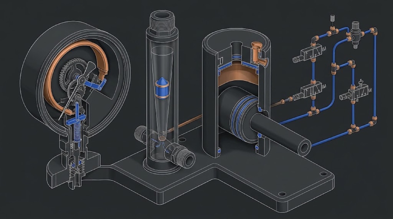
Pressure and flow are two different questions
Every gas-driven device you will service - a ventilator, an anaesthesia workstation, a suction regulator, an oxygen concentrator, a dental chair, a laboratory analyser with pneumatic valves - is built from the same few things: a source of gas under pressure, restrictions, valves that open and close paths, sensors that measure, and the volumes in between. Before any of that makes sense, two quantities must be kept apart in your head.
Pressure is force per unit area. It is the push available to move gas. Flow is the quantity of gas moving past a point per unit of time. The electrical analogy is useful and not perfect: pressure behaves like voltage, flow like current, and a restriction like a resistance. A wall outlet with nothing connected can show full pressure and deliver zero flow, just as a battery shows full voltage with no load. The moment you draw flow, every restriction between the source and your point of measurement takes away some pressure.
Most field mistakes in pneumatics come from mixing the two. 'The pressure is fine' measured on a static gauge says nothing about whether the supply can deliver the flow a ventilator demands at peak inspiration. 'The flow is set correctly' says nothing about whether the downstream pressure is high enough to open a valve. Always ask which of the two the complaint is really about, and measure that one, under the conditions in which the fault appears.
Gauge, absolute and differential pressure
A pressure value means nothing until you know what it is referenced to. Gauge pressure is measured relative to the surrounding atmosphere: an open port reads zero. Absolute pressure is measured relative to a perfect vacuum: an open port reads the barometric pressure, roughly 101 kPa at sea level and noticeably less at altitude. Differential pressure is the difference between two points, and it is what most flow sensors actually measure.
Equipment documentation, gauges and service screens do not always say which they mean. Pipeline and cylinder pressures are almost always gauge values. Gas laws only work with absolute values. Oxygen sensors respond to the partial pressure of oxygen, which depends on absolute pressure. When two readings disagree by about one atmosphere, the first suspect is that one is absolute and the other gauge. Suction equipment adds another source of confusion: vacuum is often shown as a negative gauge pressure, sometimes as a positive number labelled 'vacuum', and the sign convention differs between devices.
Units you will meet and how to convert them
Medical equipment from different markets uses different units for the same quantity, sometimes on the same machine: supply pressure in kPa, bar or psi; airway pressure in cmH2O, hPa or mbar; vacuum in kPa, mmHg or inHg; flow in L/min or mL/s. Learn the handful of conversions below well enough to do them in your head to two significant figures, and always write the unit next to every number you record. A number without a unit in a service report is not a measurement.
- 1 bar = 100 kPa = 1000 hPa = 1000 mbar, about 14.5 psi.
- 1 psi is about 6.89 kPa; 50 psi is about 345 kPa or 3.45 bar.
- 1 cmH2O is about 0.98 hPa (98 Pa); for airway pressures hPa, mbar and cmH2O differ by about 2%.
- 1 kPa is about 10.2 cmH2O; 1 mmHg is about 0.133 kPa or 1.36 cmH2O.
- Standard atmosphere = 101.325 kPa = 1.013 bar, about 760 mmHg or 14.7 psi.
- 1 L/min is about 16.7 mL/s; 60 L/min = 1 L/s.
- Flow is also reported at different gas conditions (ATPS, BTPS, STPD, or 'standard litres'); check which before comparing two readings.
The gas laws an engineer actually uses
Boyle's law says that, at constant temperature, pressure times volume is constant for a fixed amount of gas, using absolute pressure. This gives the everyday estimate of cylinder content: free gas volume is roughly the cylinder's water capacity multiplied by the cylinder pressure in bar (gauge pressure is close enough for an estimate at high fill pressures). A 10-litre cylinder at 150 bar holds roughly 1500 litres of gas at atmospheric pressure. Real gases deviate at high pressure and the label or the supplier's table is the authority, but the estimate is good enough to tell a nurse whether a cylinder will last a transfer. It does not work for nitrous oxide or carbon dioxide stored as liquid: their cylinder pressure stays nearly constant until the liquid is gone, so content is judged by weight.
The temperature laws say that for a fixed volume, absolute pressure rises and falls in proportion to absolute temperature. You meet this in two places. A cylinder left in the sun reads higher than one in a cool store. And in leak testing, gas compressed quickly into a closed volume heats up, then cools back to room temperature and its pressure drops - which looks exactly like a leak if you start the timer too early. Lesson 7 returns to this.
Dalton's law says that the total pressure of a mixture is the sum of the partial pressures of its components. Oxygen sensors measure partial pressure, not percentage. At altitude, or when a sensor sits in a pressurised part of a circuit, the same 21% gas produces a different partial pressure and a different sensor output. That is why oxygen sensors are calibrated where and how they are used, and why some machines compensate for barometric pressure.
How gas flows through a restriction
Gas flowing slowly and smoothly through a long, narrow passage is laminar: the pressure drop is proportional to flow, and very sensitive to the passage diameter - in a round tube it depends on the fourth power of the radius, so halving the bore of a hose or a sense line increases its resistance about sixteen times. Faster flow through short orifices and bends becomes turbulent: pressure drop then rises roughly with the square of flow. A partially kinked hose or a dirty sintered filter behaves well at low flow and collapses at high flow; this is why you test supplies under flow.
When the upstream absolute pressure through a small orifice is roughly twice the downstream absolute pressure or more, the flow through it becomes choked: the gas reaches the speed of sound in the narrowest section and the flow stops depending on the downstream pressure. Designers use this to make simple, stable flow sources - a fixed orifice fed from a regulated pressure gives a nearly fixed flow regardless of what is connected after it. For you, it means two things: that flow depends directly on the regulated pressure feeding the orifice, so a drifting regulator drifts the flow; and that a partly blocked orifice reduces flow without any other symptom.
Reading a pneumatic diagram
Service documentation shows the gas path as a pneumatic diagram. Manufacturers use symbols based on ISO 1219-1, the international standard for fluid power graphic symbols, with their own variations. The diagram is a map of function, not of physical layout: two valves drawn side by side may be on opposite sides of the machine, and one block on the drawing may be a manifold with ten parts. Diagrams are drawn in the rest state - power off, no pressure, springs extended - so a normally closed valve is drawn closed.
A valve is drawn as one square per switching position. Inside each square, arrows show the flow paths and T-shapes show blocked ports. The square that touches the connecting lines is the rest position; imagine the squares sliding over when the valve is actuated. The name '3/2 valve' means three ports and two positions. Actuators are drawn at the ends: a spring, a solenoid (a small rectangle with a diagonal line), a pilot line, a manual button. Port numbers follow a common scheme in industrial pneumatics - 1 for supply, 2 and 4 for outlets, 3 and 5 for exhausts - but medical manufacturers often use their own labels, so read the legend.
- Solid line: main gas path. Dashed line: pilot or control line, or sensing line.
- Circle with an arrow: pressure gauge. Diamond with a line: filter; with a drain: water separator.
- Ball on a V-seat: check (non-return) valve; with a spring, it needs a cracking pressure to open.
- Square with an offset arrow, a spring and a dashed pilot from the inlet: relief valve.
- Narrowing between two curves: fixed restrictor; with a diagonal arrow through it: adjustable.
- Square with a spring and pilot from the outlet: pressure regulator (reducing valve).
- Valve with a slanted arrow across the actuator or envelope: proportional (infinitely variable) valve.
Fifty that looked like nothing
A ward reported that a newly delivered ventilator, imported from another market, showed an oxygen supply pressure of about 50 on its status screen, and the staff believed the pipeline was failing because their wall gauges showed values in the hundreds. The hospital's gas team was called out, and a request for an urgent repair was raised. The engineer opened the machine's settings and found the supply pressure unit set to psi. 50 psi is about 345 kPa, inside the ventilator's stated inlet range and consistent with the wall gauge. No fault existed. The engineer changed nothing inside the machine, explained the conversion to the charge nurse, recorded the finding and asked the hospital to confirm with the distributor whether the display unit could be changed to kPa in configuration.
Before diagnosing a pressure problem, confirm the unit and the reference. Write the unit next to every number you record.
Four point eight of what?
A request reached a service engineer: an anaesthesia workstation failed its gas supply test 'although the oxygen pressure is 4.8 kPa'. Read literally, 4.8 kPa is almost no pressure at all; the writer probably meant bar or kgf/cm². Other reports from the same fleet gave pressures as '4 kg', '233 cm' or simply '50'. The engineer asked for each reading with its unit and the screen it came from, then measured the outlet pressure with a calibrated gauge while the machine drew flow and read the inlet pressure on the service screen. Both values were converted to one unit and compared with the specification. Only then was it clear whether the supply was low or the machine's inlet regulator or sensor was at fault.
A pressure without a unit is not data. Write the unit every time and convert to a single system before comparing with the specification.
On-site checklist
- Carry a conversion card for kPa, bar, psi, cmH2O, hPa, mmHg and L/min.
- Write the unit and 'gauge' or 'absolute' next to every pressure you record.
- Use a calibrated reference gauge whose range suits the measurement (do not read 5 cmH2O on a 10-bar gauge).
- Measure supply pressure under flow, not only static.
- Keep the pneumatic diagram of each model you service, with your own notes on physical locations.